|
Introduction
Legged
robot systems have been studied in theory and built since the late
1960’s. Their advantage over wheeled vehicles apply when there is
a need to isolate the moving platform from ground irregularities and
negotiate highly uneven terrain. By using discrete
“footholds”, this isolation may result in obtaining
straight line motion for their bodies, independent from the terrain
irregularities.
Their capacity to negotiate a variety of terrain types make
them ideal for applications where prepared surfaces are not
available. Such situations may be found in natural environments
(forests, desert, etc) as well as in human-made environments ( house
interiors with stairs etc).
A key issue for the wide use of such systems relies on their autonomy,
which on turn depends on their energetics, ie their ability to operate
with low energy requirements during their locomotion. This is difficult
to obtain with such multi-dof systems as power losses often occur in
oscillatory motion of their limps. HTR has been focusing on energetics
of legged platforms during the past years. Energetically efficient
legged systems are difficult to design, both from mechanical,
electronics and control point of view, as all these three factors play
a role in the power requirements of the resulting system. HTR has
designed since 1996 several mid-scale quadrupedal systems (1.2m, 20kg)
with remarkable energetics. The design of the larger QU1120 platform
has been the purpose of a long development based on the experience
gained on prior mid scale projects.
Opposite to wheeled vehicles, the energy requirements of legged
platforms are not in direct function to their size. This is due to the
fact that legged platforms use discrete footholds and therefore do not
suffer from wheel friction problems when in contact with dusty, uneven
soil, or covered with small stones etc. They can theoretically operate
with their centre of gravity moving on a straight line, therefore
needing zero energy for the displacement.
This results to the possibility to use a larger legged platform, such
qs the QU 1120, which in turn would provide a better ground negotiation
capacity, larger area of operation as well as a possibility to
transport important payloads during operation.
The choice of the correct actuation and power control units are also of
key importance. QU1120 takes advantage of HTR’s long test
periods with a wide variety of electrical actuation solutions. Two
energy-consuming key areas have to be addressed during operation
of legged systems: Actuators working against gravity forces (such
as the leg actuators supporting the body weight) and actuators
performing oscillating motion (such as the leg actuators performing the
fore-aft motion of the legs).
In both cases an optimised selection of actuation and power control
designs provide solutions for best performance. The resulting QU1120
machine has fully acceptable energetics for slow motion (in
the range of 140W for slow walking), for its 75kg of weight (of which
8kg battery).
With a length exceeding 2m, the machine can easily carry its own
1m² solar panel and become completely autonomous for outdoor
applications.
Detailed Specifications
Robot code name: QU 1120 / 25
QU: Quadruped
25: Nominal power of dc motors
Physical dimensions
Overall length : 2130mm
Height : 1257 mm
Battery autonomy: minimum 2 hours
Total number of motors: 12
Height at hip level: 920mm
Width at foot base: 450mm
Mass
Net full robot weight without batteries : 67kg
Battery: 8 kg
Motors as follows:
- 12 basic mobility motors (3 per leg) for fully autonomous walking
Power control servo card and micro-controller unit
MC300 MOTORCARD SPECIFICATIONS
A. FUNCTIONAL DESCRIPTION
The card is composed from:
1. Central processing unit 80C592.
2. CAN-BUS TRANCEIVER PCA 82C250.
3. Analogue processing unit
4. Parameter modification unit.
5. PWM power DRIVER unit .
B. SPECIFICATIONS
1. CENTRAL UNIT.
There are 7 CONTROL MODES available for the dc motor
control
1.1 P FOR POSITION FEEDBACK
1.2
PI
“
1.3
PD
“
1.4
PID
“
1.5 POSITION & FORCE FEEDBACK
1.6 POSITION & VELOCITY FEEDBACK
1.7 POSITION, FORCE, VELOCITY FEEDBACK
The card communicates with similar units through CAN (Control Area
Network) protocol and exchanges a frame of 2 variables and 6
control parameters with a rate of 1Mbaud
- MAX PROCESSING TIME FOR A FULL OP. CYCLE (WITHOUT
COMMUNICATIONS DELAY TIME): LESS THAN 1ms.
2. CAN-BUS TRANCEIVER
-
FULLY COMPATIBLE WITH “ISO/DIS 11898”
STANDARD.
- UP TO 1 MBAUD
- BUS LINES PROTECTED AGAINST TRANSIENTS
- SLOPE CONTROL TO REDUCE RADIO FREQ. INTRFERENCES
- THERMAL PROTECTION
- SHORT CIRCUIT PROOF.
- 110 NODES CAN BE CONNECTED.
Other communication: RS232 9pin
3. UNIT OF ANALOGUE PROCESSING
- GAIN ADJ.
- OFFSET ADJ.
- FILTERING
UNIT of PWM POWER DRIVER
- Frequency
(PWM) : 15KHZ
-
MAX OPERATING
VOLTAGE
: 24V
-
MAX CONTINUE
CURRENT
: 20A
-
MAX PULSED
CURRENT
: 120A (MAX PULSE WIDTH 3ms
FOR 24 V )
-
MAX OUTPUT CONT.
POWER : 300W
Onboard Sensors
The machine is equipped with analogue position sensors for all axis as
well as force sensors built in the mechanical structure of the system
(HTR patents pending).
Plans

Assembled Chassis of QU1120 with legs
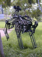
Photos from integrated system

Completed prototype during tests


Detail of motor for lateral motion of leg during tests
Control architecture
The QU1120 control is based on the creation of a network of 12 MC300
power cards, each one of which controls a single DOF of the machine,
using hybrid (force-position) control strategy.
The network is supervised by another 4 micro-processor based cards, each one of which deals with the following tasks:
- Card 1 : System supervision, communications, start up, shutdown
- Card 2: Gait generation
- Card 3: Stability
- Card 4: Obstacle avoidance
Communications with a remote control centre are made over wireless RS-232 for general type commands (direction of motion etc).
Gait generation comprises walking and trot gaits.
Stability is monitored and controlled through measurements of the force sensor inputs of the machine.
Obstacle avoidance is based on ultra sound obstacle detection.
|